1. ROOM PREPARATION
Before taking the scan, make sure there is enough space in the room. You should be able to walk around the patient to scan their entire torso.
The distance from the patient can vary depending on the sensor used to take the scan, but it typically needs to be at least 25 centimeters away.
It is also best to do the scan in a place with good natural light.
2. EQUIPMENT SETUP
Option 1: If you already have the 3D scan
If you already have 3D model files, you can skip this step and upload them directly to the website (backscnr.com) - see How to analyze a scan taken with a different app.
The BackSCNR platform is compatible with .stl, .obj, .ply, and .glb files.
Option 2: If you don't have the 3D scan
The equipment needed to take a scan are:
- BackSCNR iOS app
- iPad or iPhone
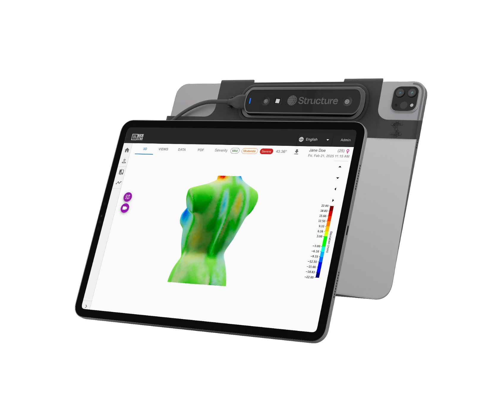
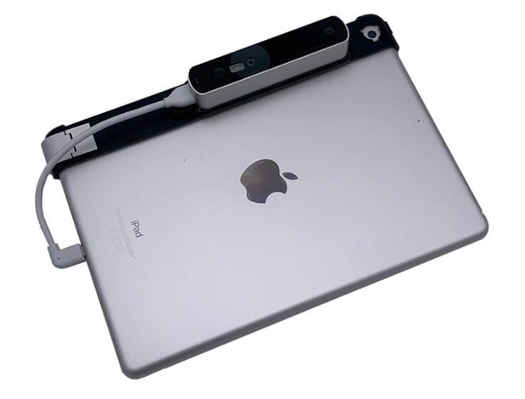
- Structure sensor
To start capturing patient scans, download the BackSCNR iOS app from the App Store. It is compatible with iPad (recommended) and iPhone.
Currently, the app requires either a Structure Sensor or an iPhone with a TrueDepth sensor to capture the 3D scans. If your iPhone supports Face ID then it has a TrueDepth sensor. The app is compatible with Structure Sensor 3 (recommended) and some older models.
For troubleshooting, refer to their support team and documentation. You can also check the known issues tracker.
Before capturing scans, it is important to calibrate the sensor to ensure high-quality models. Follow the Structure recommendations.
3. PATIENT PREPARATION
Before taking the scan, make sure:
- The trunk must be visible.
- The upper body should be bare or wearing a sports bra.
- The hair should be tied back if necessary.
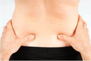
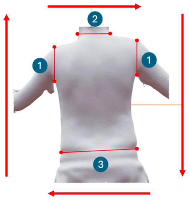
- Adjust the patient's pants or shorts to the level of the posterior superior iliac spine (PSIS), the palpable bones just above the hips (see image).
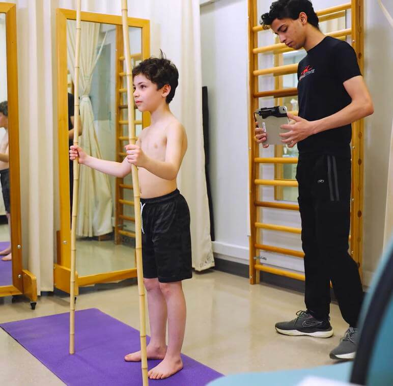
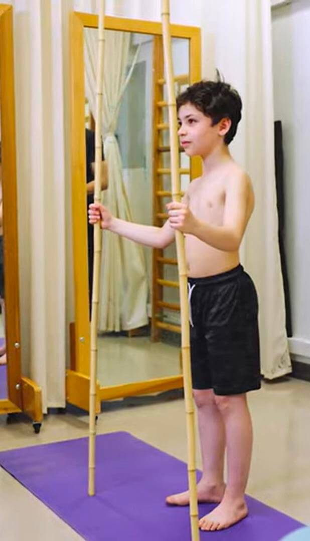
While the scan is being captured:
- It is recommended that the patient stand tall with their arms slightly apart and remain in this position.
- To keep the scapular and shoulder muscles relaxed, we suggest holding two sticks while taking the scan.
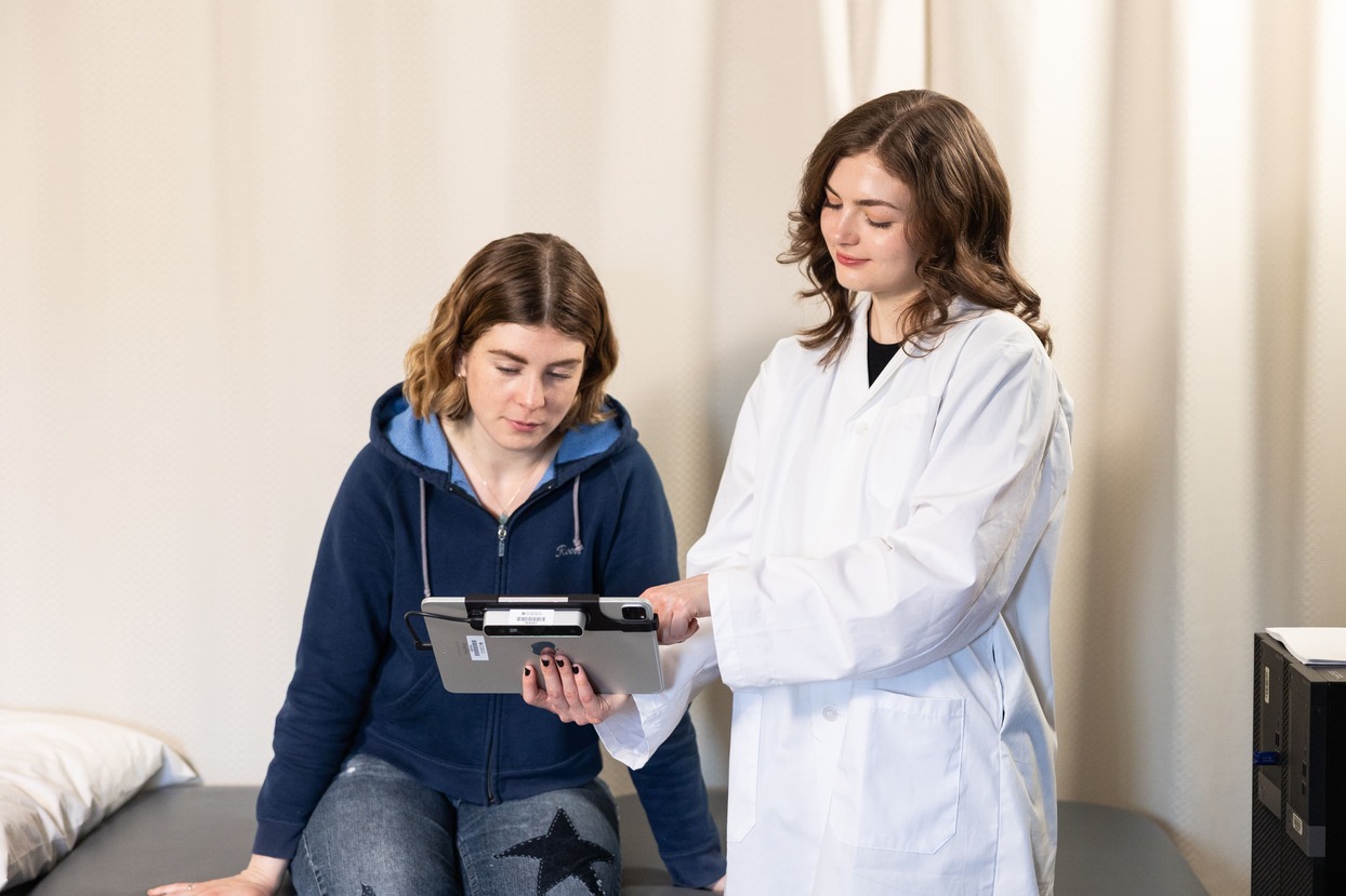
4. USING THE BACKSCNR APP TO SCAN
BackSCNR is committed to accessibility, offering multiple scanning methods to suit your various needs.
| Scanning Option | Requirements | Accuracy |
|---|---|---|
| Structure Sensor | iPhone/iPad + Structure Sensor | Most Accurate |
| Truedepth App | iPhone with Face ID (iPhone X or later) | Accurate |
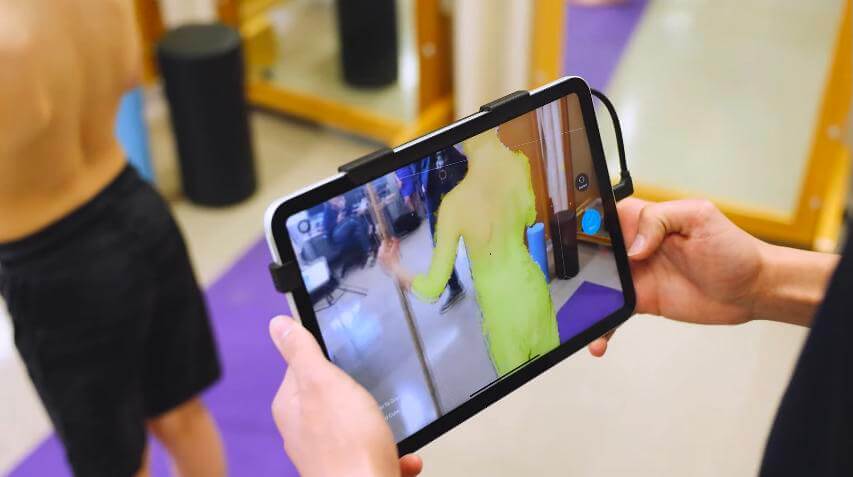
Option 1: Using Structure Sensor
- Connect the sensor to your iPad or iPhone and ensure that it is connected to the Internet.
Note: You can still capture the scan without an internet connection. However, you'll need to connect to the internet to upload it to the BackSCNR platform. - Open the BackSCNR app and follow the on-screen instructions to capture the scan.
- Keep a proper distance to capture the full torso.
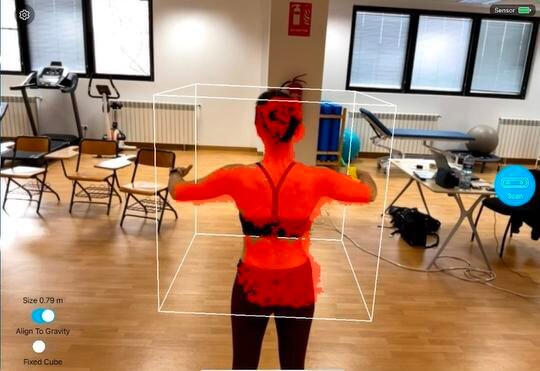
- Walk 360° around the patient, starting from the back, so the exported model is correctly oriented.
- The cube on the screen shows the scan area. You can adjust its size with two fingers. Red areas on the cube indicate the body parts detected for scanning, which will turn white as the scan is being captured.
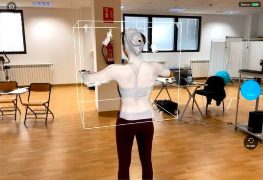
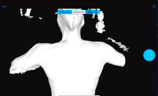
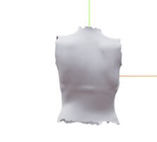
- After completing the 360° scan of the patient, click the blue 'Done' button on the right. On the next page, check if the 3D model adequately captures the patient's torso. A high-quality 3D model is completely white with no visible gaps in the mesh. If the 3D model is not high-quality, click 'Back' to scan the patient again.
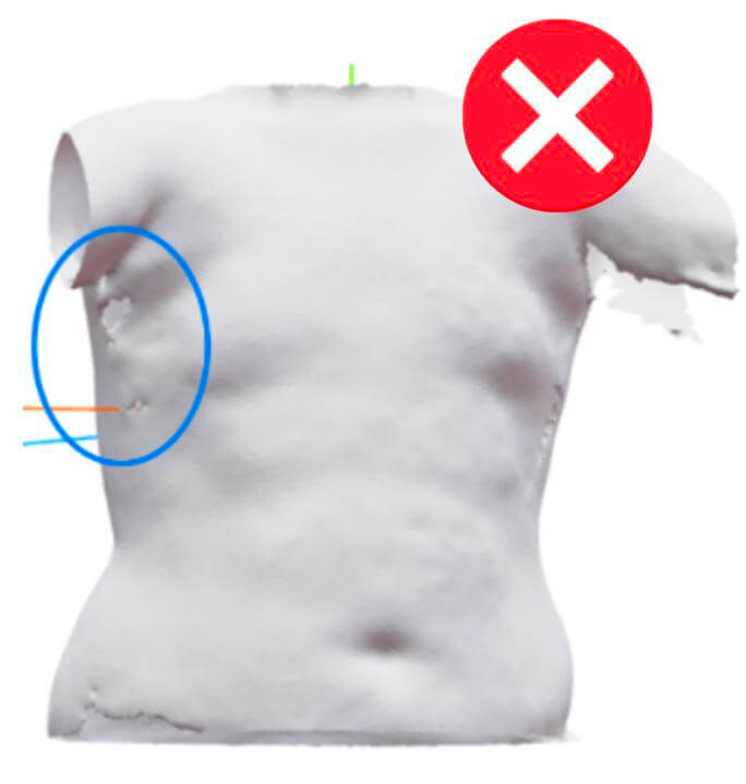 Not high-quality scan
- If the model is satisfactory, click the blue 'Submit' button on the right side of the screen. The time it takes to submit the 3D model depends on the internet connection.
- After submitting the model, save the patient's information.
Option 2: Using TrueDepth App (iPhone only)
A scan can be performed using only an iPhone equipped with a TrueDepth sensor. If your iPhone supports Face ID, it is compatible!
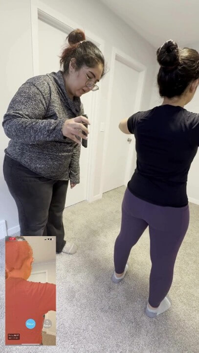
- Open the BackSCNR app and follow the on-screen instructions to capture the scan. TrueDepth uses the front-facing (selfie) camera, so the screen must face the patient during the scan.
- Maintain a proper distance from the patient to keep the full torso within the frame.
- Walk 360° around the patient, starting from the back, so the exported model is correctly oriented.
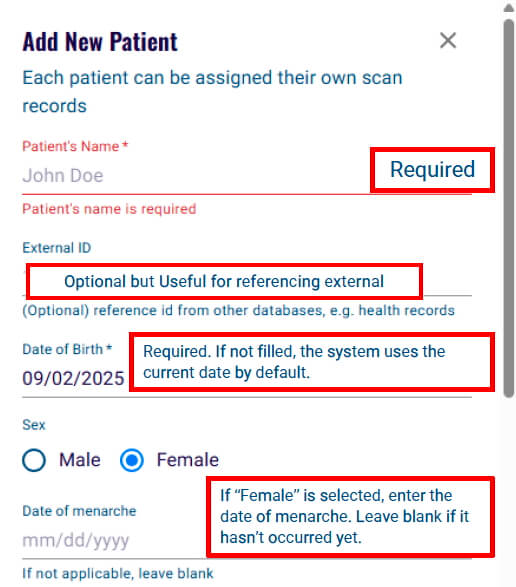
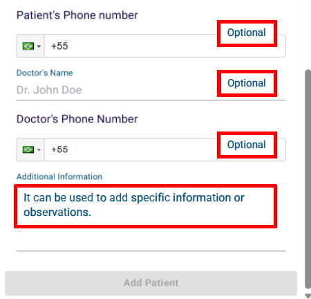
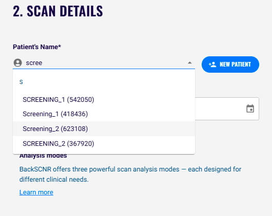
5. SAVING PATIENT'S INFORMATION
After uploading a new scan, using the BackSCNR iOS app, or uploading a .stl, .obj, .ply, and .glb file, you need to save the patient's information:
6. ANALYSIS MODES
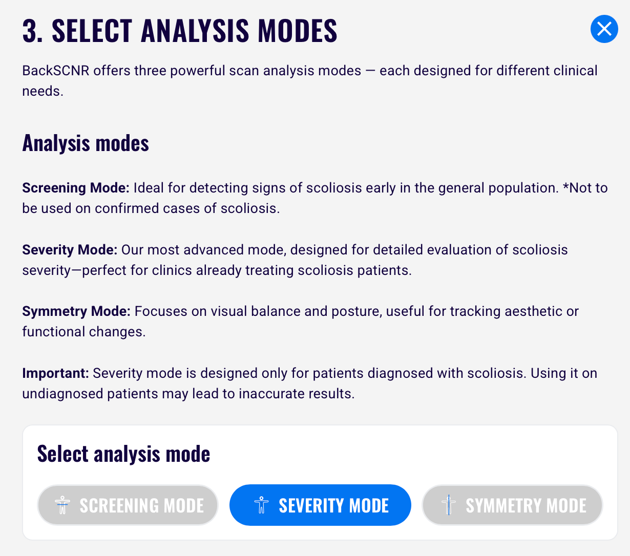
The next step after uploading the 3D model is to choose one of the three analysis options. BackSCNR presents three modes for analyzing the scan:
- Screening: Used in the initial assessment to detect signs of scoliosis. This model should not be applied to patients with confirmed scoliosis, especially those with high Cobb angles. Since our screening model was trained on data from healthy individuals and patients with mild scoliosis, it is not accurate for patients with high Cobb angles.
- Severity: This mode is used to predict the maximum Cobb angle and determine scoliosis severity based on the Cobb angle prediction. The model performs best in patients with Cobb angles between 15° and 45°. We are continuing to improve its performance and expand its applicable range.
- Symmetry: It is used to visualize the symmetry on any 3D model and was developed for general use. This mode does not provide any information related to scoliosis screening or severity.
Note: If you are using the BackSCNR iOS app to upload a new scan, you must select an assessment option to save the 3D model to your account. If you skip this step, your model will not be saved. Once saved, you can complete the analysis later.
7. CROPPING
Option 1: Auto Crop
After you select an analysis mode, an automated crop is performed on your scan. Compare the original scan with the auto-cropped result to verify that no important areas have been removed.
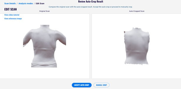
A proper auto-crop should:
- Completely remove all arm portions at the armpits.
- Remove the neck and chin area, leveling the top of the scan with the shoulders.
- Remove everything below the waistband/pants line while preserving as much of the hip area as possible.
After reviewing the auto-crop, you can:
- Accept the auto-crop: Continue editing on the auto-cropped mesh. You can still manually refine the crop afterward to remove any remaining unwanted areas.
- Perform a manual crop: Edit the original uploaded mesh by following the manual crop instructions below.
Option 2: Manual Crop
After you choose the mode of analysis, it is required to crop the 3D model. You need to:
- Remove all arm portions at the armpits completely.
- Crop the neck and chin area to be level with the shoulders.
- Cut off everything below where the pants begin but keep as much of the hip area as possible.
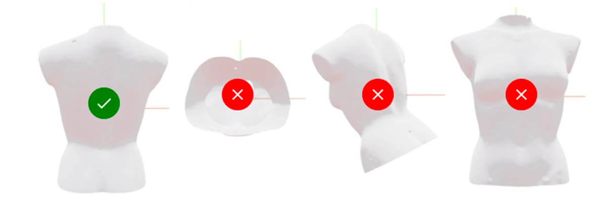
Here are a few common mistakes and correct examples:
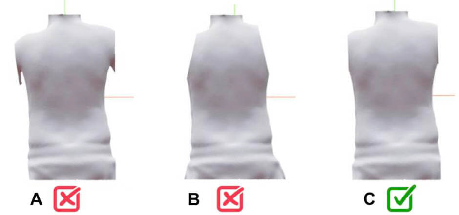 A: arm parts remain visible; B: too much shoulder removed; C: correct example
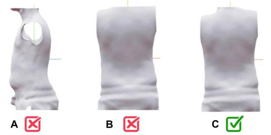 A: neck parts remain visible; B: shoulder parts removed; C: correct example
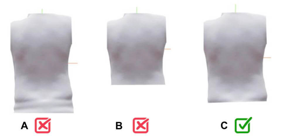 A: pants texture remains; B: too lower torso removed; C: correct example
Note: Cropping is an important step to ensure accurate results. Our models have been trained only by analyzing the torso without the neck or arms. Therefore, everything else should be removed for the analysis.
Note: The complete cropping process (arms, pelvis, and head/neck) should be performed in a clockwise direction.
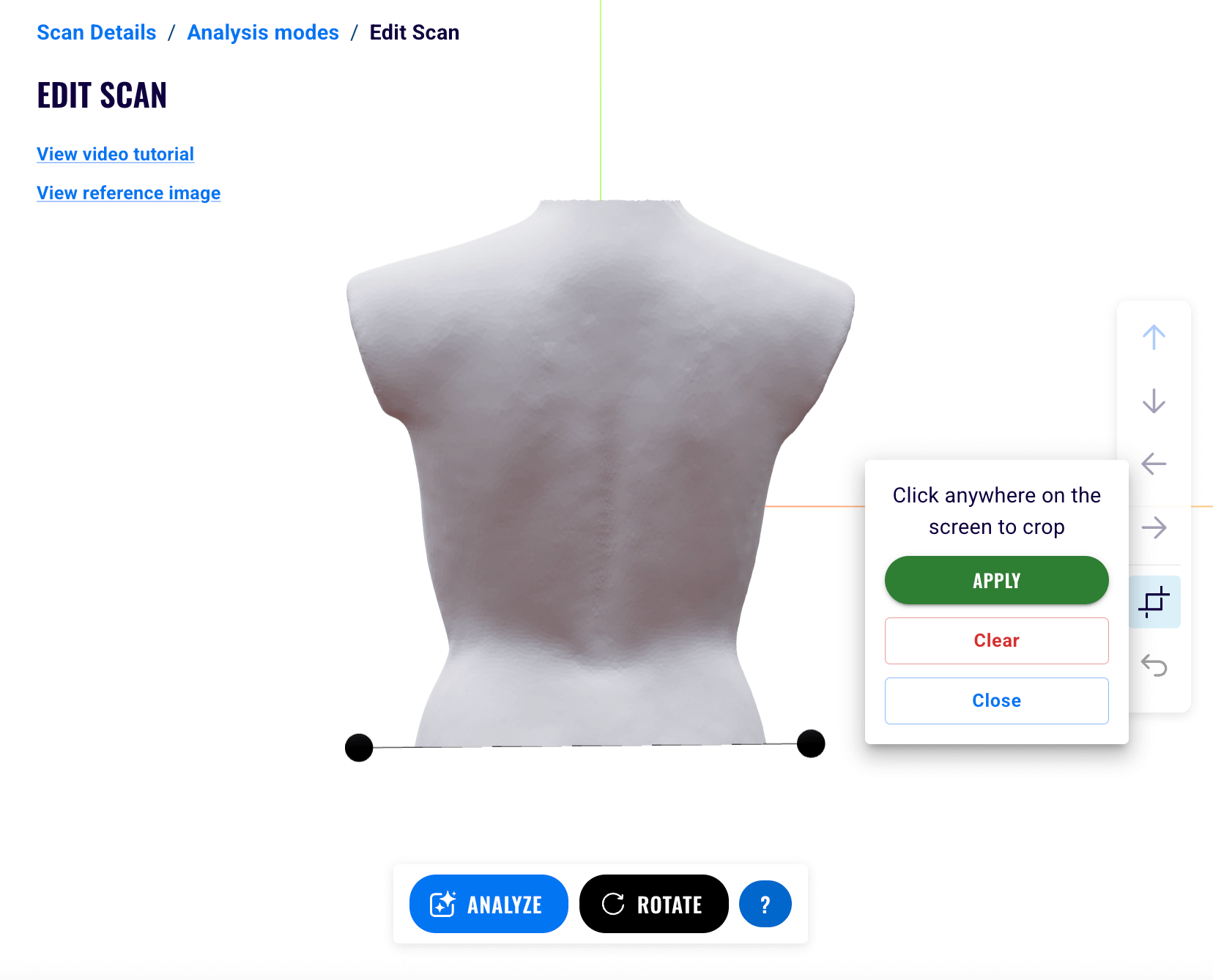
To start cropping, click the crop button in the bottom right and follow these steps:
- Click anywhere on the screen to place the first dot.
- Then, click again in another location to place the second dot.
- The dots will be connected by a line that crops the mesh:
- Place the dots in a clockwise manner.
- At least 2 dots are required to apply a crop.
- An infinite number of dots can be added.
- Click on Apply to apply and save the crop.
- Click on Clear to discard the changes by removing all the dots.
- Click on Close to close the tool.
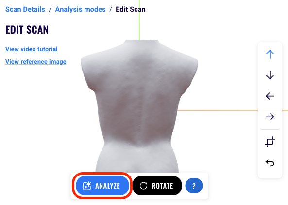
8. ALIGNMENT
To analyze the 3D model, ensure that it is upright and that the displayed image shows the back of the torso. If not, use the tools provided to reorient the torso appropriately.
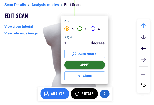
The 'Rotate' button allows you to rotate the torso. Click on Rotate to rotate your mesh by a specified angle in degrees along the x, y, and z axes. The green axis (y) points up and the blue (z) axis points from the front towards the back of the model. Follow these steps:
- Select either the x, y, or z axis to rotate about.
- Enter the rotation angle in degrees.
- You can enter negative angles.
- You can click on the up/down arrows to add/subtract 90 degrees.
- Repeat steps 1 and 2 for the other axes, if needed.
- Click on Auto to automatically rotate.
- Click on Apply to apply and save the rotation.
- Click on Close to close the tool.
- Once you have finished editing your model, click on Analyze to submit the mesh for analysis. This may take a few minutes, and you will be redirected to the results once the analysis is complete.
9. ANALYZING THE RESULTS
After analysis, results appear in the toolbar under the tabs: 3D, Views, Data, PDF, Sagittal plane, and Insights.

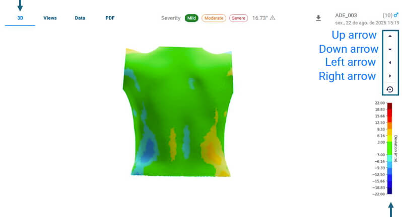
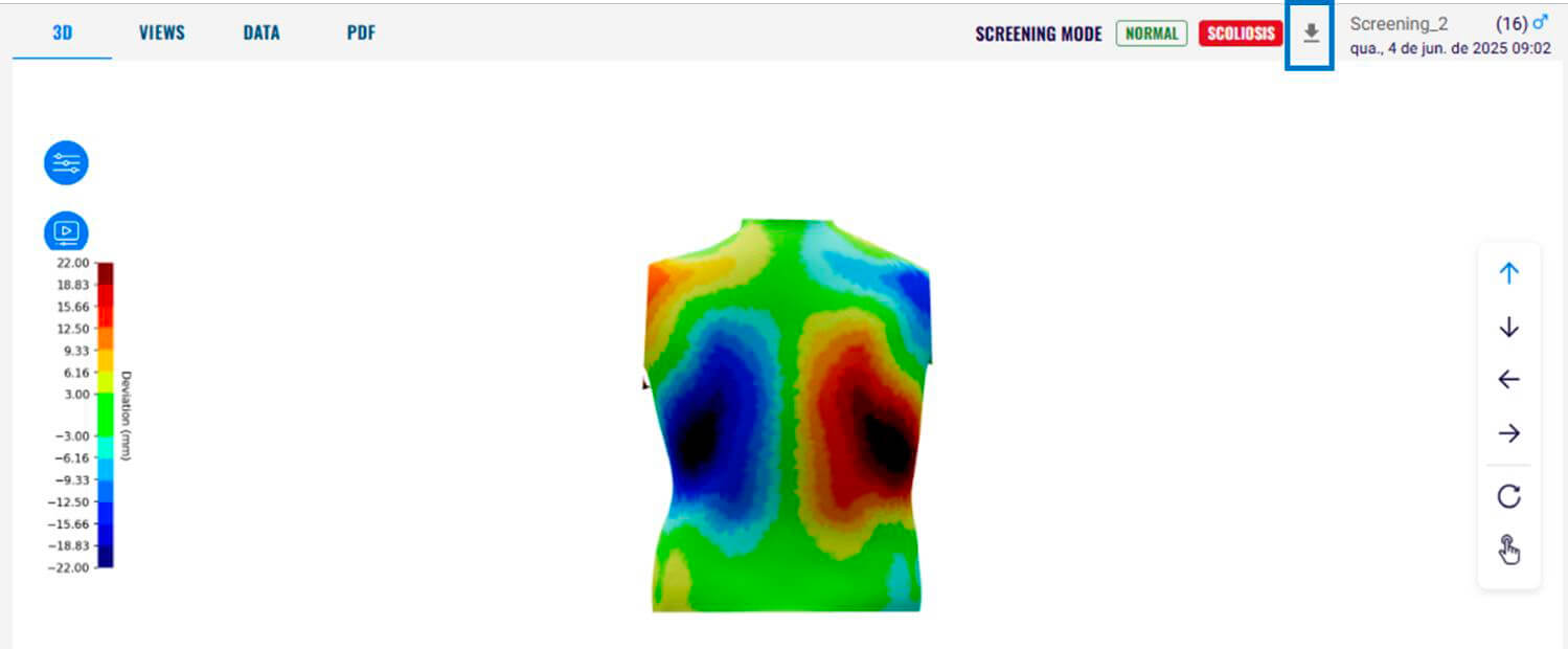
3D Tab
The 3D view lets you rotate, zoom, and pan the model. The color bar on the right shows deviation in millimeters, where red indicates gibbosity, and blue indicates depression, with color intensity representing the magnitude of deviation.
You can rotate the model by dragging it to the right or left, or by using the options on the right side of the screen. The up arrow provides a back view, the down arrow provides a front view, the left arrow provides a left side view, the right arrow provides a right side view, and the circular arrow automatically rotates the model.
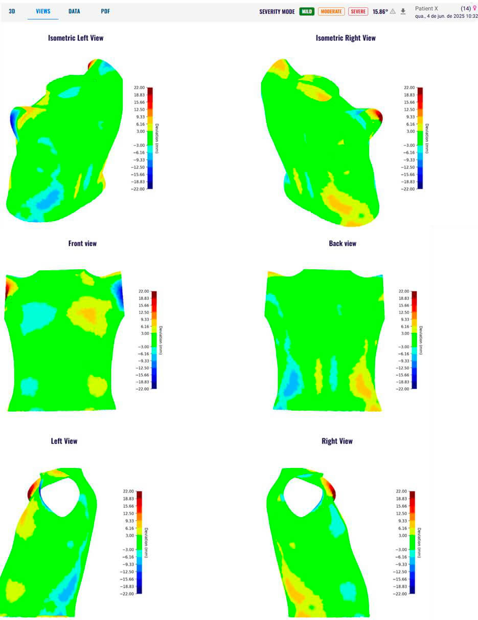
Views Tab
The Views displays 2D images of the model, including isometric left and right views (which show all three axes of a 3D model in a 2D image), as well as front, back, left, and right views. These views also show a color bar representing deviation in millimeters. Red indicates gibbosity and blue indicates depression, with color intensity representing magnitude of deviation.
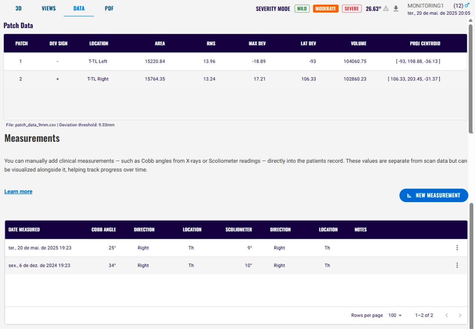
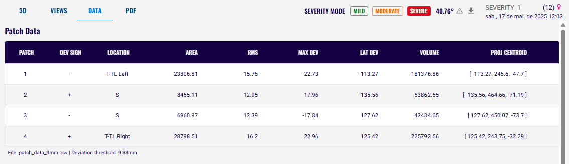
Data Tab
This tab provides detailed information about each patch. Patch information shows the patch information and its interpretation. If you enter the patient's clinical measurements (e.g. Cobb angle and scoliometer information), they will also be displayed in the Data tab. See Adding patient's clinical measurements to input the patient's clinical measurements.
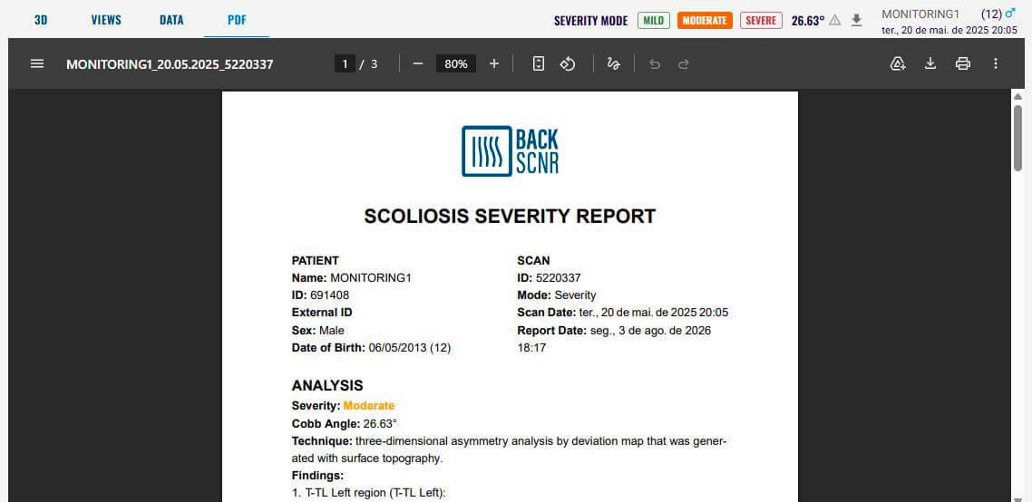
PDF Tab
This tab allows you to download the PDF report related to the analysis. Information about the PDF clinical report and its interpretation is available in Pdf clinical report.
Further Information
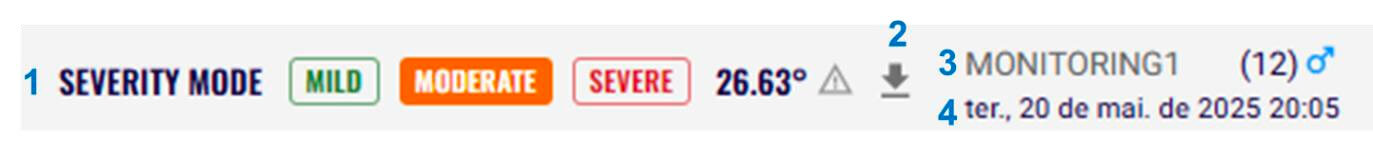
- Classification: Displays the screening mode or Cobb angle.
- If you use the Screening mode, the result indicates whether the patient has normal posture or scoliosis. The result is highlighted.
- If you use the Severity mode, the AI-predicted Cobb angle is displayed, as well as the severity based on the AI-predicted Cobb angle:
- 0º - 10º → Spinal curve
- 10º - 20º → Mild Scoliosis
- 20º - 45º → Moderate Scoliosis
- Above 45º → Severe Scoliosis
- The severity classification is also highlighted.
- Symmetry mode does not provide a classification because its purpose is to visualize asymmetry in a 3D model for general use.
- Download Files: Export the 3D model, image, and CSV files.
- Patient Information: Name, age, sex, etc.
- Scan Date/Time: When the scan was taken.
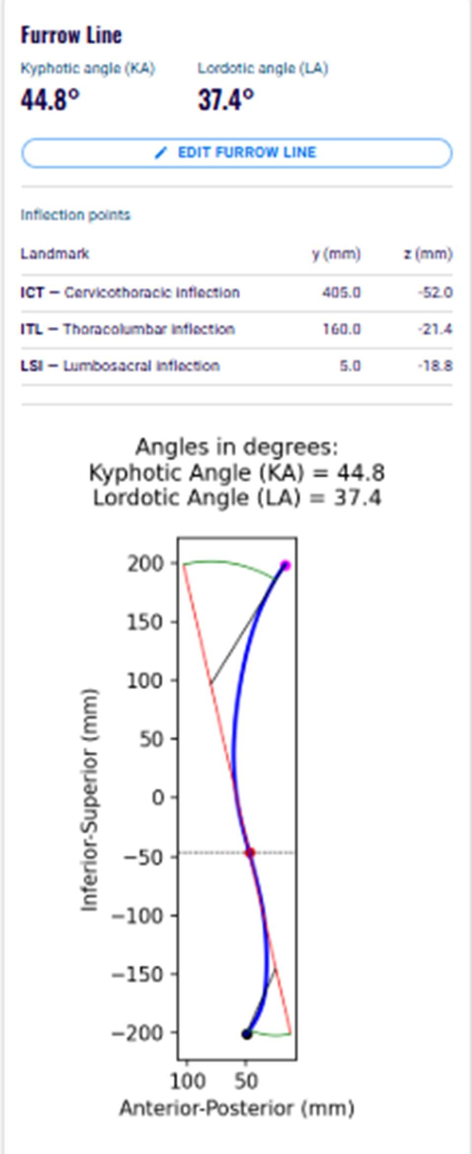
Sagittal Plane Tab
This tab displays the projection of the sagittal plane on the analyzed mesh, along with the estimated kyphotic angle (KA) and lordotic angle (LA).
The sagittal plane is a reference line traced along the center of the back surface, following the natural spinal contour of the trunk. It is used to estimate spinal curvature and calculate the kyphotic and lordotic angles from surface topography.
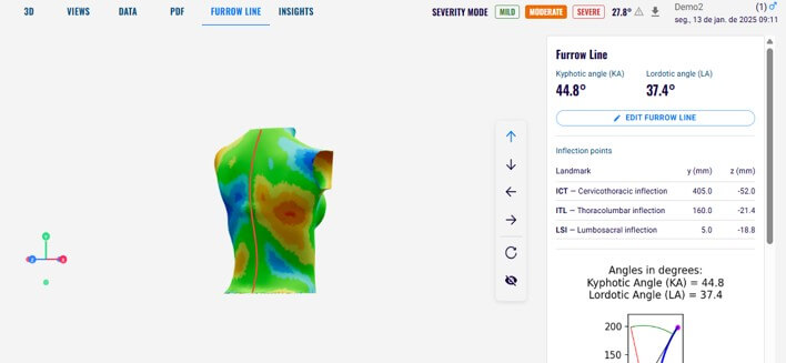
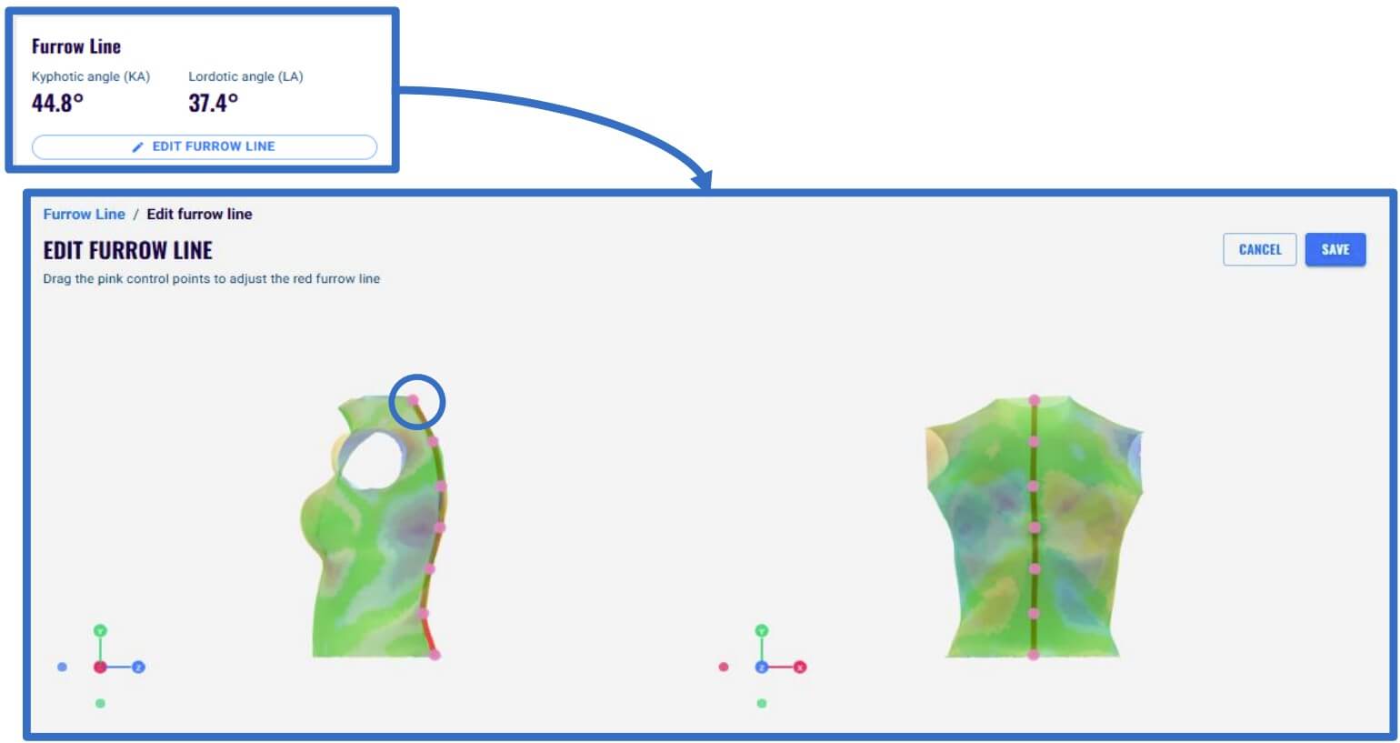
The sagittal plane is represented by the red line on the model. It can be manually adjusted to better fit the trunk surface. Since the kyphotic and lordotic angles are calculated from the sagittal plane, editing the line may change these angles.
To edit the sagittal plane, click the Edit spine line button, then adjust the line by clicking and dragging the points as needed. After completing the adjustments, click Save.
This tab also displays the inflection points and the positions of the represented landmarks.
Insights Tab
This tab displays aesthetic measurements based on trunk asymmetry. The RMSE quantifies the overall asymmetry of the trunk surface.
The tab shows the overall RMSE percentile relative to the selected population (scoliosis or healthy), along with regional asymmetry measurements for the upper thoracic, mid-back, and lower back regions, including their corresponding percentiles within the selected population.
The selected population is highlighted in blue.
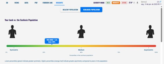 Overall RMSE percentiles
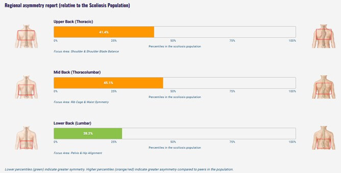 Regional asymmetry report
10. ADDING PATIENT'S CLINICAL MEASUREMENTS
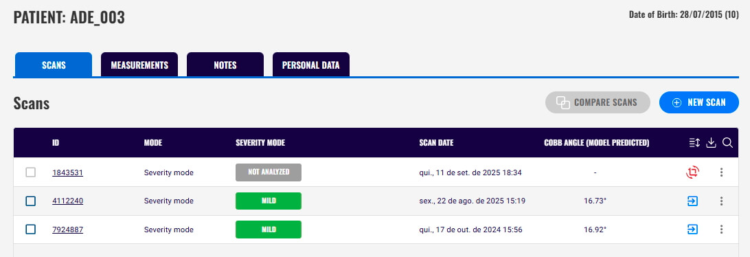
The Medical Record displays the list of patients who have been assessed. Select the patient to whom you want to add clinical measurements.
On the patient's page, the tabs are:
- Scans: Displays all scans taken, the mode used for analysis, the classification (if the scan was analyzed), the scan date, and the AI-predicted Cobb angle (if the scan was analyzed using the Severity mode).
- Measurements: Displays the patient's clinical measurements.
- Notes: Allows you to add notes related to the patient and displays all saved notes.
- Personal Data: Displays the patient's information and allows you to edit their personal data.
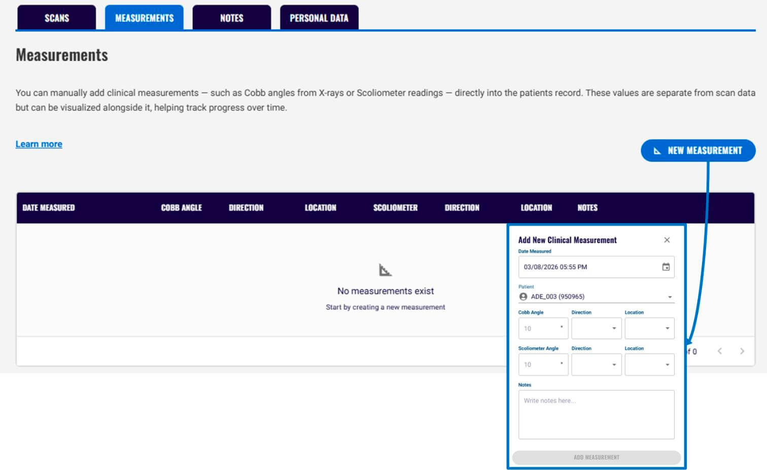
To add a clinical measurement:
- Go to the Measurements tab and click New Measurement.
- Add the Cobb angle (from an X-ray exam), the scoliometer angle, their direction (left or right), and location (lumbar - L; thoracic - Th; thoracolumbar - Th-L; and upper thoracic - U-Th).
- Select the date these measurements were assessed. If you do not select a date, the current date will be registered by default.
After adding the clinical measurements, they will be displayed in the Measurements tab.
11. HOW TO REANALYZE A SCAN USING A DIFFERENT MODE
You can analyze the same 3D model using a different mode. To do so:
- After analyzing the 3D model, download the file by clicking the download arrow in the top-right corner. You'll need this file to upload the 3D model to the BackSCNR platform.
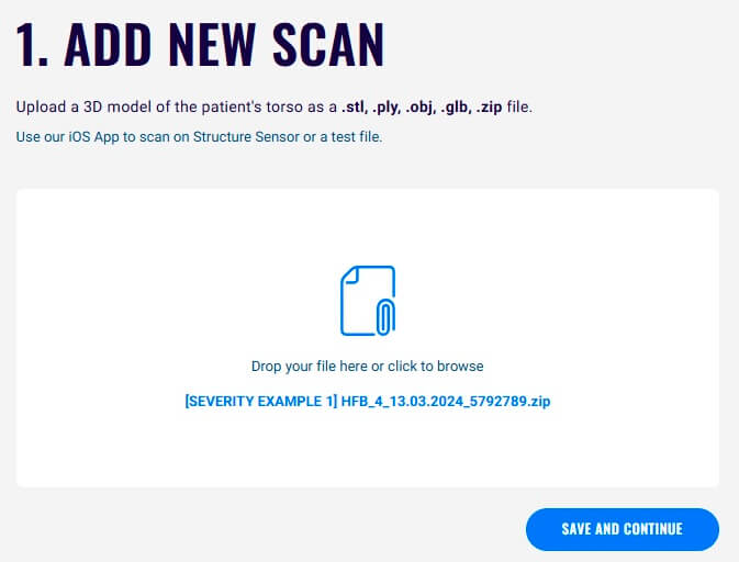
- Go to Home and select New Scan on the right side of the screen. Then, choose the file (.stl, .ply, .obj, .glb, or .zip).
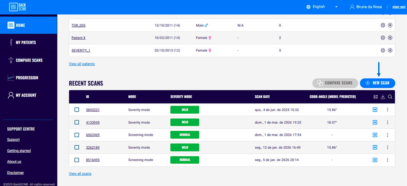
- It is not necessary to enter the patient's information again. If you are uploading a scan from a previously assessed patient, you can find them in your patients list.
- Choose the mode in which you want to analyze the new scan and then follow the same analysis steps. See Analysis modes, Cropping, and Alignment for analysis.
12. HOW TO ANALYZE A SCAN TAKEN WITH A DIFFERENT APP
You can analyze a scan taken with a different app.
Note: The BackSCNR platform supports .stl, .ply, .obj, .glb, and .zip files.
To do so:
- Save the file to your device.
- On your home page, select New Scan on the right side of the screen. Then, choose the file on your device, and click on Add Scan.
- Then, follow the steps to save the patient's information (see Saving patient's information) or add a saved patient (see How to reanalyze a scan using a different mode).
13. CHECKING PATIENT'S PROGRESSION
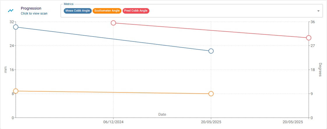
With BackSCNR, you can track a patient's progression over time. You need at least two scans of the same patient taken at different times and analyzed using severity mode.
To do so:
- Select the Progression tool from the panel on the left side of the page.
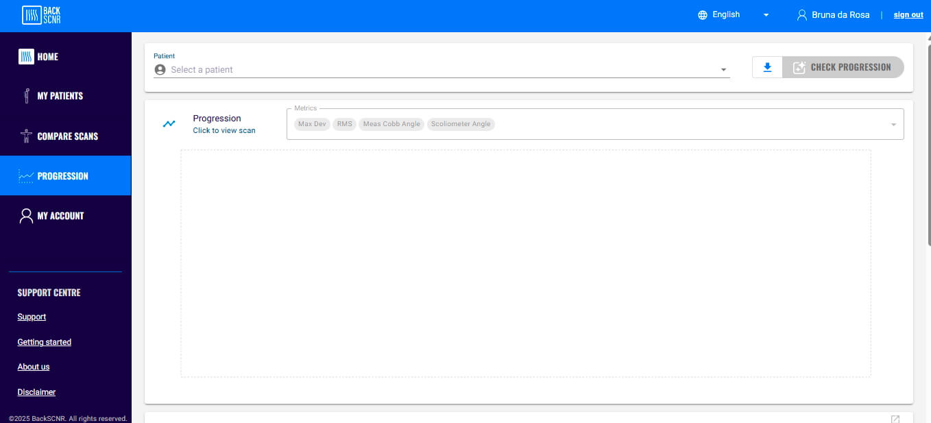
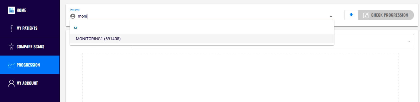
- Select the patient whose progression you want to check from your patient list.
- In the Metrics panel, you can select the measurements you want to track. You can track patch information (see Patch information for details on how to interpret it), the AI-predicted Cobb angle, and clinical measurements added to the patient's information, such as the Cobb angle measured on an X-ray and the scoliometer angle.
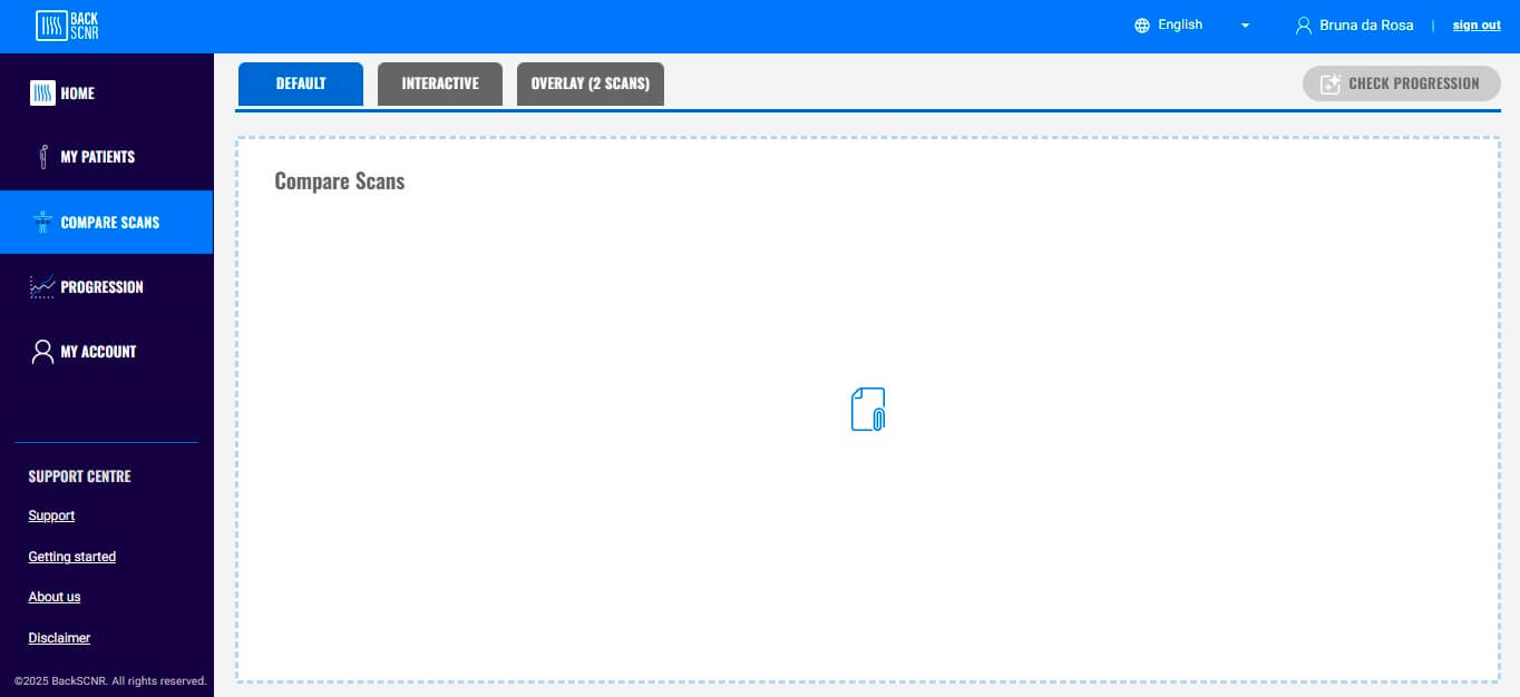
14. COMPARE SCANS
You can also compare the scans taken over time. To do so:
- Select Compare Scan tool from the panel on the left side of the page.
- Click on + and select the patient from the list. After selecting the patient, choose the first scan to add to the analysis, then click Add Scan.
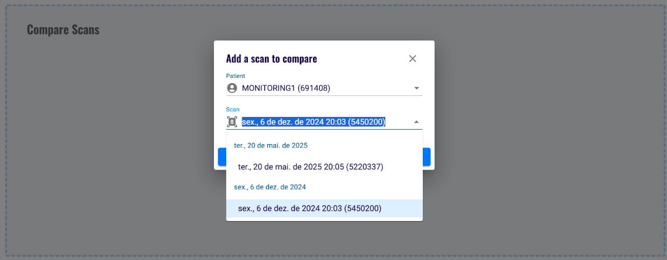
- Follow the same steps to add a second scan to the analysis.
Note: If you have more than two scans to compare, repeat these steps for each additional scan.
- To compare scan results effectively, the platform provides three distinct tabs:
- On Default tab, you can see all information results (see Analyzing the results to see the results displayed).
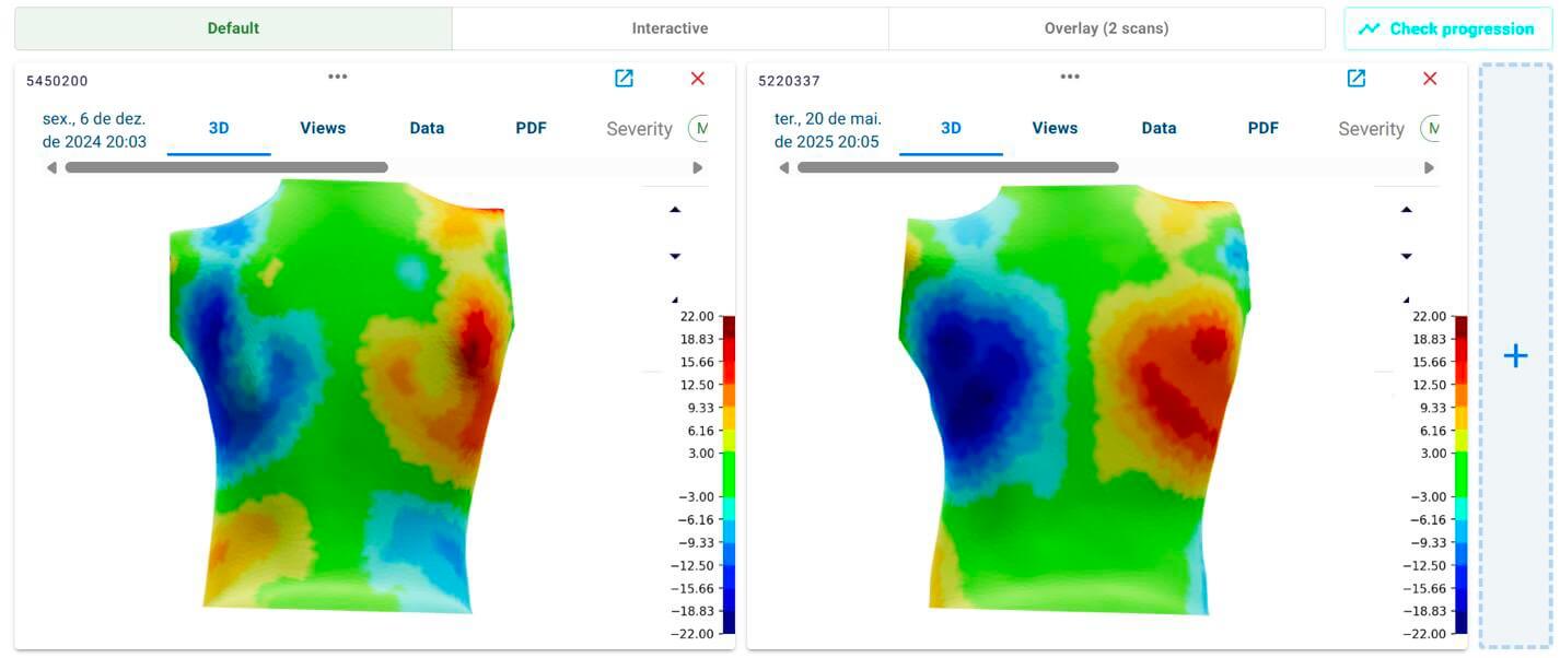
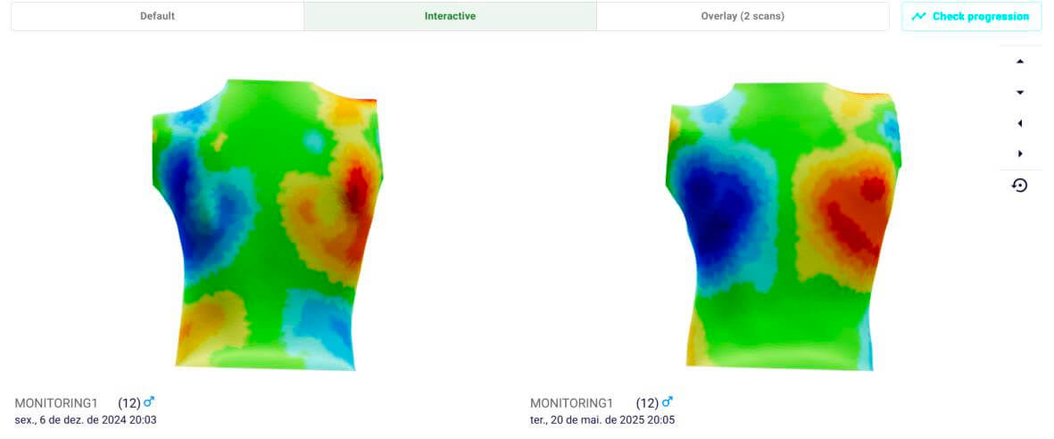
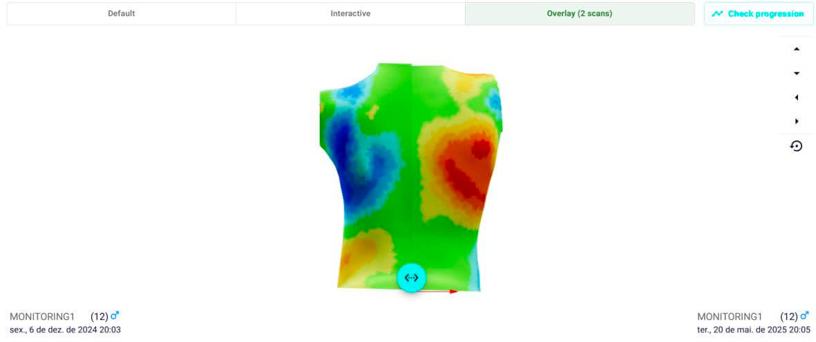
- On the Interactive tab, you can view all 3D scans together.
- On the Overlay tab, you can see two scans superimposed.
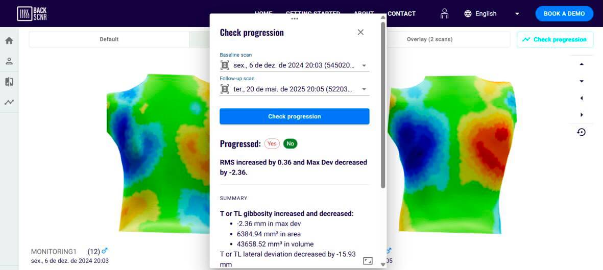
The Check Progression button uses our progression model, which was developed to identify scoliosis progression based on a comparison of two scans. This model provides information about whether scoliosis has progressed, based on the patch parameters. For an explanation of patch parameters, see Patch information.
15. DEVIATION COLOR MAP INFORMATION
The Deviation Color Map (DCM) displays the identified asymmetries in the patient's torso and their magnitude. Green represents areas of symmetry. Blue and red represent asymmetric areas and are correlated with spinal curvature in scoliosis.
Blue represents depressed areas, and the darker the blue, the greater the depression. Red, orange, and yellow represent gibbosity areas, and the darker the color, the higher the gibbosity.
On the right side of the screen, a graphic displays the magnitude of the asymmetric areas (blue or red) in millimeters. Negative values indicate a more anterior asymmetric area (depression), while positive values indicate a more posterior asymmetric area (gibbosity).
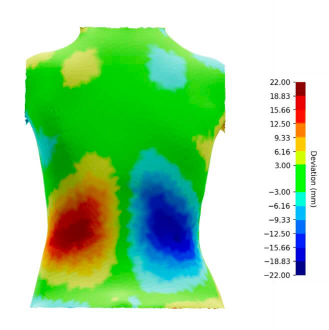 Note: This image shows a patient with a gibbosity on the left side of the lumbar region and a depression on the right.
16. PATCH INFORMATION
In BackSCNR analysis, a 'patch' is an area of asymmetry that is detected. These areas are numbered for your reference.
BackSCNR provides quantitative information about these areas of asymmetry, or patch parameters.
| Parameter | Description | Units |
|---|---|---|
| Location | Region of the detected patch | T = thoracic T-TL = thoracolumbar L = lumbar |
| Area | Size of the detected asymmetry patch | mm² |
| RMS | Root mean square of surface deviations within the patch | mm |
| Maximum deviation (MaxDev) | Largest gap between the torso surface and its mirrored version within the patch* | mm |
| Lateral deviation (LatDev) | Distance from the torso centerline to the patch center | mm |
| Volume | Volume between the original and reflected torso surfaces within the patch | mm³ |
* MaxDev refers to the point on the original torso that shows the largest difference compared to the reflected torso, within a specific patch.To detect asymmetric areas, BackSCNR divides the torso down the middle and creates a mirrored version.
- In non-scoliotic torsos, the reflected torso looks very similar to the original, with only small differences.
- In scoliotic torsos, because of asymmetries, there are noticeable differences between the original torso and its reflection.
** Positive values indicate the deviation is to the right, negative values indicate the deviation is to the left.
After analyzing a scan, you can view the patch parameters by following these steps:
- On the Results page, click the 3D tab, then click Interactive Mode. The identified patches will be displayed on the model. Click a patch to view its parameters.
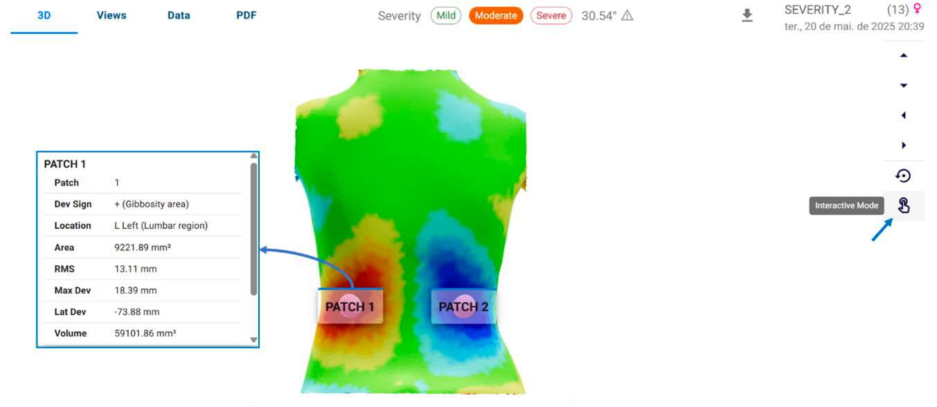
- Alternatively, you can click the Data tab to view all the patch information.
17. PDF CLINICAL REPORT
BackSCNR provides a clinical report summarizing the information based on the analysis. See Analyzing the results for instructions on how to access it.
In the severity mode analysis, the information presented in the clinical report includes:
- Patient's information: name, sex, date of birth, and menarche.
- Scan information: mode used to the analysis, scan date, and report date.
- Classification of severity: based on the AI-predicted Cobb angle (see more details in Analyzing the results).
- Findings: main findings based on the patch parameters. For more information about the patch parameters, see Patch information.
- Conclusion: about the severity of scoliosis, based on the AI-predicted mode and the patch parameters.
- 3D views: present the DCM on front view and back view. For more information about the DCM see Deviation color map information.
In the screening mode analysis, the information presented in the clinical report includes:
- Patient's information: name, sex, date of birth, and menarche.
- Scan information: mode used to the analysis, scan date, and report date.
- Classification of screening: see more details in Analyzing the results.
- Findings: main findings based on the patch parameters. For more information about the patch parameters, see Patch information.
- Conclusion: about the screening, based on findings.
- 3D views: present the DCM on front view and back view. For more information about the DCM see Deviation color map information.